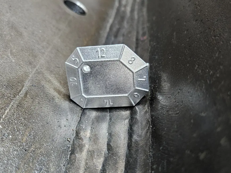
Ultrasonic testing (UT) of welded joints
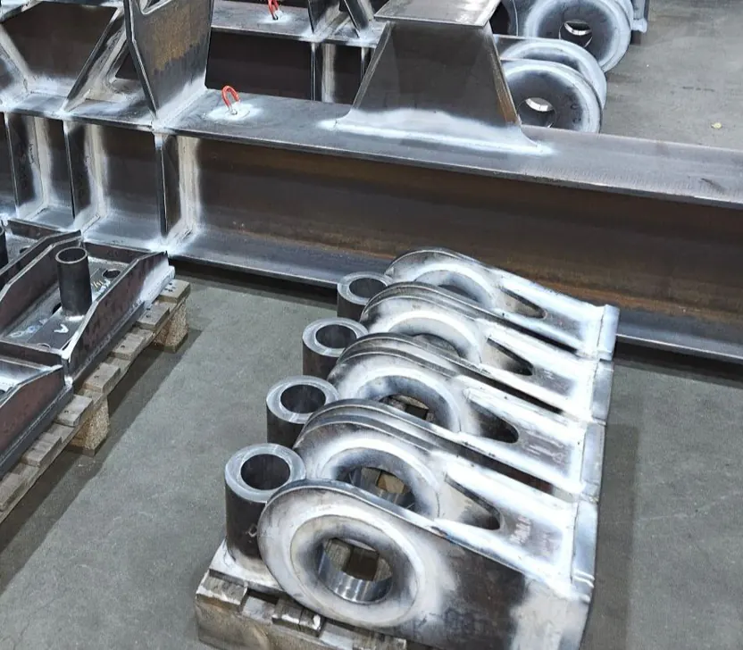
Ultrasonic testing is the method of choice when you need to find planar defects: cracks, lack of fusion and incomplete penetration. Those are structurally the most dangerous imperfections, because they form a sharp notch from which a fracture can grow. Where radiography shows the weld as a shadow image, ultrasonics measures sound reflected from an interface, and a planar defect is an excellent mirror.
UT is also portable, gives immediate results, needs no radiation exclusion zone and can be applied from one side. The downside: the result depends heavily on operator competence and on a properly written procedure. This article covers the principle, the technique to ISO 17640 and how to keep the execution under control.
The principle and the angle probe
A piezoelectric element converts an electrical pulse into a sound wave of typically 2 to 5 MHz. That wave travels into the material, reflects off an interface and returns. Time of flight gives distance, amplitude gives a measure of the size of the reflecting surface.
For welds an angle probe is almost always used, at 45, 60 or 70 degrees. The beam enters at an angle, reflects off the back wall and so covers the full weld cross section while the probe is moved across the plate surface beside the weld. The weld cap itself is acoustically unfavourable and is therefore bypassed rather than penetrated.
Calibration and reference blocks
Before each test series the equipment is set up on a reference block. The V1 block to ISO 2400 and the V2 block to ISO 7963 serve to check the time base, the index point and the beam angle. In addition a reference block of the same material and thickness with artificial reflectors, often side drilled holes, is used to build the sensitivity curve.
That curve, the DAC or the AVG/DGS method, corrects for the fact that an identical flaw at greater depth returns a weaker signal. Without such a curve the amplitude of an echo has no meaning. Calibration is therefore not a formality but the basis of every evaluation, and it is repeated at the end of the series to rule out drift.
ISO 17640 and the testing levels
ISO 17640 covers testing of welds in steel and defines four testing levels, A to D. Level A is the lightest, with limited scanning angles and coverage. Level B is the usual level for quality level B to ISO 5817. Level C imposes additional requirements, for example removing the weld cap so it can be scanned over, and level D is a tailored examination for special cases.
The testing level follows from the product standard or specification. Acceptance criteria are not in ISO 17640 but in ISO 11666, which sets permitted echo height and indication length per level. That distinction is frequently confused: 17640 says how you measure, 11666 says what is acceptable.
Where UT falls short
Coarse grained and highly attenuating material, such as austenitic weld metal and castings, scatters the sound and makes conventional UT practically unusable. That calls for low frequency dual element probes or a different method altogether.
Geometry works against you too: below roughly 8 mm the beam becomes too wide relative to thickness, and complex shapes and attachments create geometric echoes that can be mistaken for defects. An operator who does not understand the geometry reports indications that are not defects, or worse, dismisses a real defect as geometry.
From conventional to phased array
Conventional UT gives an A-scan: a trace on the screen interpreted by the operator. Little remains as evidence beyond the report. Phased array and TOFD produce images that can be stored and re-evaluated later, and cover the cross section in a single pass.
As a result mechanised UT increasingly replaces radiography on piping and heavy walled structures, with the added benefit that no radiation exclusion zone is required. See phased array and TOFD.
Control in practice
Because the result stands or falls with the operator, UT requires a written procedure referencing the standard, the probes, the calibration blocks, the scanning levels and the reporting. That procedure is written by a level 3 to ISO 9712 and executed by a level 2.
During an inspection it pays to have the calibration demonstrated and a known reflector pointed out. That takes ten minutes and says more about the reliability of the report than the report itself. DEHAAS carries out that verification as part of NDT coordination and vendor inspection.
Frequently asked questions
For planar defects such as cracks and lack of fusion, yes; for volumetric defects such as porosity and for the archival image, RT is stronger. They often complement each other. The choice belongs in the NDT plan, based on the expected defect types and their structural significance.
In practice from about 8 mm; ISO 17640 applies from 8 mm wall thickness. Below that the beam becomes too wide and the entry echo overlaps the defect. For thinner walls, high frequency phased array, eddy current or radiography are used.
Only with adapted technique. Austenitic weld metal has a coarse, oriented solidification structure that scatters and deflects the sound. Special low frequency dual element probes, or TOFD set-ups qualified for the purpose, are required. A standard carbon steel procedure is unsuitable.
Common practice is to calibrate at the start of the series and repeat every four hours and on every change of probe, cable or instrument, plus a final check. If the final check deviates beyond the permitted margin, the work since the last valid check must be repeated.
More from the knowledge centre
Have a welding or QA/QC question?
Ask the DEHAAS Welding & Quality Assistant, have your case reviewed by a specialist, or call us directly.