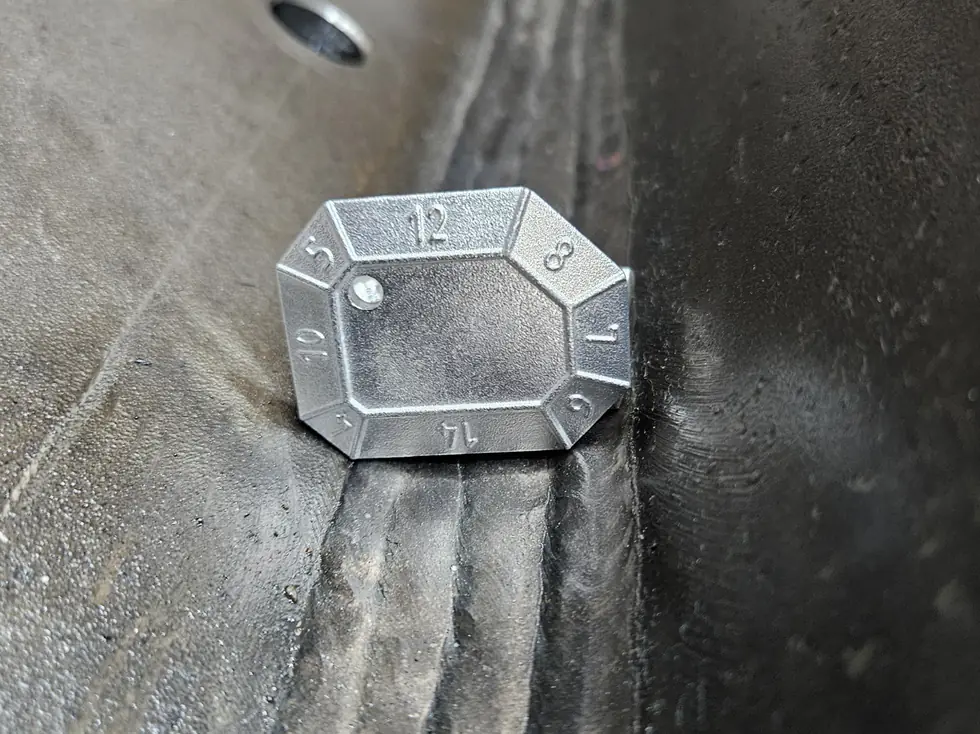
Phased array and TOFD
Phased array and TOFD are the two ultrasonic techniques that have pushed back radiography on piping and heavy walled structures over the past twenty years. Both produce a stored image, both need no radiation exclusion zone, and both cover the weld cross section in a controlled scan rather than by hand.
They measure very different things, however. Phased array steers the beam electronically and builds a sector image; TOFD measures the time of flight of diffracted waves from the tips of a flaw and so measures its height accurately. In practice they are often deployed together.
Phased array in brief
A phased array probe contains not one piezoelectric element but an array of, say, 16, 32 or 64. Driving those elements with small time delays steers and focuses the beam electronically. Without moving the probe you can sweep a range of angles, for example from 40 to 70 degrees.
The result is a sector scan: a fan shaped image of the weld cross section in which a flaw appears at its true position. With an encoder measuring position, the scan is tied to the weld circumference so you know exactly where an indication lies. ISO 13588 sets the requirements for application and levels.
TOFD in brief
In TOFD two probes face each other across the weld, a transmitter and a receiver. Between the lateral wave along the surface and the back wall echo lies a time window. If a flaw is present, sound diffracts around its tips and two additional signals arrive: one from the upper tip and one from the lower.
The time difference between them gives the flaw height with an accuracy conventional UT cannot match, often better than 1 mm. That height is decisive for a fracture mechanics assessment. ISO 10863 covers application to welds. The weakness of TOFD is the dead zone just below the surface and at the back wall, covered by a supplementary scan.
Why it replaces radiography
There are four practical reasons. No radiation exclusion zone, so production need not stop. Results are immediate rather than after processing. Flaw height is measured, which radiography cannot do. And sensitivity to planar defects, precisely the dangerous type, is considerably better.
Against that, the set-up must be designed and qualified per weld configuration, and both equipment and operator cost more. For a handful of welds it does not pay; for a series of identical welds such as a pipeline or a run of vessels it wins quickly.
Qualifying the technique
Unlike manual UT, the sensitivity of a mechanised set-up cannot be taken for granted. The scan arrangement, angles, focal laws and coverage are captured in a procedure demonstrated on a coupon with known reflectors, often flat bottomed holes or implanted flaws at the critical positions.
For pressure equipment and pipelines a full technical justification is often required, proving the set-up finds the expected flaws at every depth. That exercise belongs in the planning, not in the week of the first weld. See writing an ITP.
Evaluation: amplitude or fitness for service
The classic route assesses amplitude and length against ISO 19285 for phased array and ISO 15626 for TOFD, with levels matching ISO 5817. That is the approach for ordinary structures.
Because PAUT and TOFD measure flaw height, a second route exists: assessment against fracture mechanics acceptance to BS 7910 or API 579. A flaw exceeding the workmanship limit may then be demonstrably safe. That is why these techniques are so attractive in offshore and process industry work: fewer repairs without lowering safety.
Frequently asked questions
Technically all but completely, provided the set-up is qualified. Formally the product standard must allow it; EN 13445 and most pipeline codes accept mechanised UT as an alternative, sometimes with additional conditions. Verify that beforehand, not afterwards.
PAUT steers the beam electronically and excels at detection and positioning. TOFD measures flaw height accurately through diffracted waves. They are often combined: TOFD for height, PAUT for coverage and for TOFD's dead zones.
ISO 9712 level 2 in UT with a specific endorsement for phased array or TOFD, or an equivalent such as ASNT or PCN with that endorsement. A general UT level 2 without PAUT training may not apply the technique independently.
Only with purpose designed probes and a procedure qualified on that material, because the coarse solidification structure deflects and scatters the sound. Low frequency dual matrix PAUT probes exist for this, but qualification on representative material is then no formality.
More from the knowledge centre
Have a welding or QA/QC question?
Ask the DEHAAS Welding & Quality Assistant, have your case reviewed by a specialist, or call us directly.