Radiographic testing (RT) of welded joints
Radiography is the only NDT method that produces an image anyone can still look at years later. A film or digital exposure shows volumetric imperfections in the weld: porosity, inclusions, incomplete penetration. That archival quality makes RT popular on pressure equipment and pipelines, where the image forms part of the final dossier.
At the same time RT has clear limits. Planar defects oriented perpendicular to the beam, such as cracks and sidewall lack of fusion on a steep bevel, regularly stay invisible. This article explains how the method works, how image quality is proven, which techniques exist and where RT is and is not the right answer.
The principle
A radiation source is placed on one side of the weld and a detector on the other. Radiation passing through the material is attenuated in proportion to thickness and density. Where a cavity such as a pore is present, more radiation passes and the image is darker. The exposure is therefore a shadow image of the penetrated thickness.
That immediately explains the strengths and weaknesses. A 1 mm cavity in a 10 mm wall gives a 10 percent thickness difference and shows up clearly. A crack 0.05 mm wide, lying across the beam, barely changes penetrated thickness and stays practically invisible. Align that same crack with the beam and it stands out.
X-ray or gamma
With X-ray the radiation is generated electrically in a tube. Energy is adjustable and when the power is off there is no radiation. X-ray gives better contrast and is preferred on thinner walls and in the workshop.
Gamma radiography uses a radioactive source, usually Ir-192 or Se-75, sometimes Co-60 for heavy walls. The source radiates continuously, which imposes strict shielding and supervision requirements, but the equipment is compact and needs no power. On site, along a pipe run or on scaffolding, gamma is therefore often the only workable option. Se-75 has lower energy than Ir-192 and gives better images on thinner walls with a smaller controlled area.
Proving image quality with ISO 19232
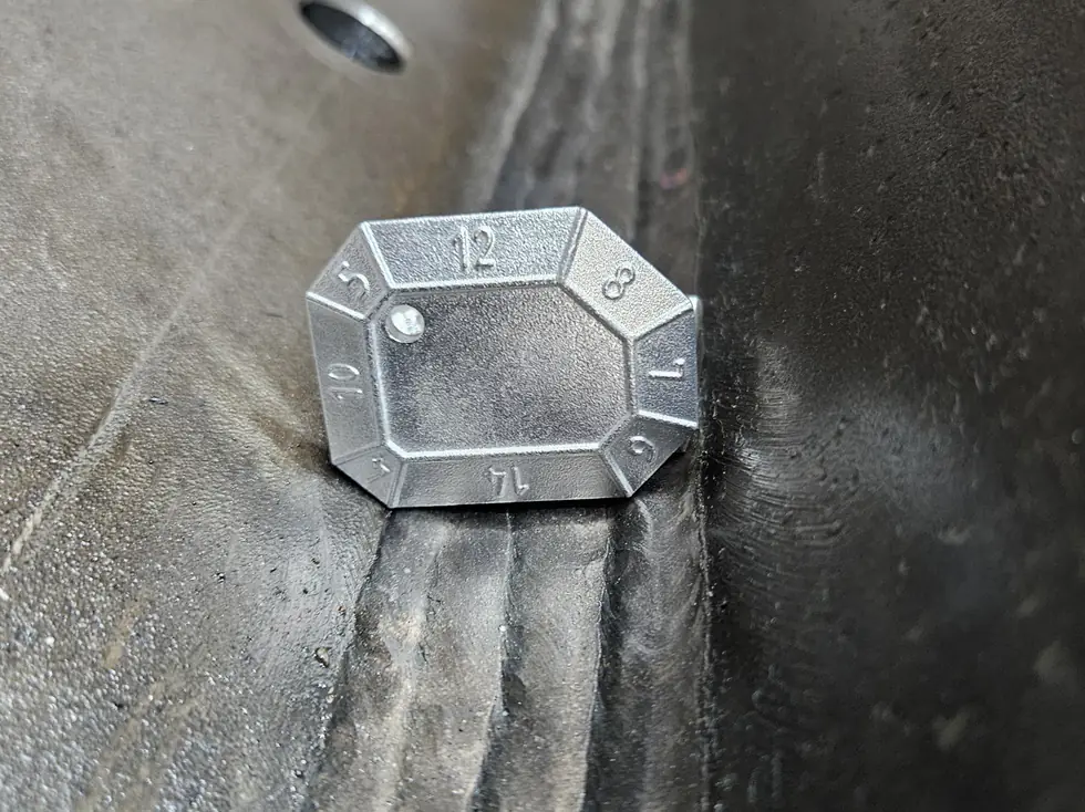
An exposure is only usable if the achieved sensitivity is demonstrable. For that you place an image quality indicator, commonly a wire IQI, on the component. ISO 19232-1 describes the wire types, part 5 the duplex wire indicator for unsharpness, and ISO 19232-3 gives the class required per thickness.
A specified wire number must be visible on the image. If that wire is not visible, the exposure is invalid no matter how attractive it looks. This is where inspections commonly fail in practice: a handsome image without a visible IQI wire is not evidence. See image quality to ISO 19232.
Techniques and set-ups
ISO 17636-1 (film) and ISO 17636-2 (digital) describe the permitted arrangements. For plate that is usually single wall exposure with source on one side and detector on the other. Pipes offer more options: double wall double image for small diameters, where the weld is projected as an ellipse, double wall single image for medium diameters, and a panoramic exposure with the source at the pipe centre where access allows.
The standard defines two classes. Class A is the basic technique, class B is improved and requires among other things a larger source to film distance and therefore longer exposure times. Which class applies is stated in the product standard or quality plan and is not for the contractor to choose.
Film, CR or DR
Classic film is increasingly being replaced by digital detection. Computed radiography (CR) uses a phosphor plate read out after exposure; the workflow resembles film but without chemistry and with immediate availability. Digital radiography (DR) uses a flat panel detector delivering the image directly.
Digital gives a wider dynamic range, keeping an exposure usable across a thickness transition. Evaluation does require a calibrated monitor and a controlled image processing workflow: contrast enhancement that polishes away indications is hard to defend in a dispute. Define which operations are allowed and retain the unprocessed file.
Evaluation and acceptance criteria
Indications are assessed against an acceptance standard. In the European framework that is ISO 10675-1, which translates the quality levels of ISO 5817 into what is permitted on a radiograph. For pressure equipment EN 13445-5 refers to it; in the ASME framework the criteria come from Section VIII and Section V.
The evaluator must be qualified to ISO 9712, typically level 2 for evaluation and level 3 for writing procedures. DEHAAS prepares NDT plans, reviews reports and supports interpretation; see NDT coordination.
Frequently asked questions
Only if the crack runs roughly parallel to the beam. Across the beam it barely changes penetrated thickness and stays invisible. For cracks and lack of fusion in heavy sections, ultrasonic testing is more reliable. See choosing the right NDT method.
That follows from the product standard and the execution class, not from a rule of thumb. EN 1090-2 gives percentages per execution class and weld type; for pressure equipment the category and the chosen conformity assessment module set the extent. Capture it in the inspection and test plan.
Only inside a shielded enclosure or within a cordoned and supervised area. Site gamma radiography requires a radiation protection expert, barriers, warning signals and often work outside production hours. That is a planning matter to arrange in advance, not on the day.
Class B is the more sensitive technique: larger source to detector distance, stricter requirements on source and image quality, and therefore longer exposures. Class B detects smaller imperfections. Which class applies is stated in the governing standard or specification.
More from the knowledge centre
Have a welding or QA/QC question?
Ask the DEHAAS Welding & Quality Assistant, have your case reviewed by a specialist, or call us directly.