Calculating and controlling heat input
Alongside the filler metal and preheat, heat input is the main control knob for the properties of a welded joint. It governs the cooling rate, and with it hardness, toughness, grain size and, in stainless steels, corrosion resistance. If you do not calculate and monitor heat input, you do not really know what weld you are delivering.
This article gives you the formula, the thermal efficiency factors per process from EN 1011-1, practical ways to measure and record heat input in production, and the reasons it matters so much for fine grain steels and stainless. It also covers the role of heat input in procedure qualification to EN ISO 15614-1.
The heat input formula
Heat input Q in kilojoules per millimetre is calculated as Q = k times (U times I times 60) divided by (v times 1000), where U is arc voltage in volts, I is welding current in amperes, v is travel speed in millimetres per minute and k is the thermal efficiency factor of the process.
A worked example for MAG welding: 28 volts, 260 amperes, 350 mm per minute. Q = 0.8 times (28 times 260 times 60) divided by (350 times 1000) = 1.0 kJ/mm. Watch the units: many errors come from mixing centimetres and millimetres per minute, or from failing to measure travel speed per run when weaving.
Efficiency factors per process
Not all arc energy ends up in the workpiece. EN 1011-1 assigns the relative thermal efficiency k:
- Submerged arc welding (121): k = 1.0
- Manual metal arc (111): k = 0.8
- MIG/MAG with solid, flux cored or metal cored wire (131, 135, 136, 138): k = 0.8
- TIG and plasma (141, 15): k = 0.6
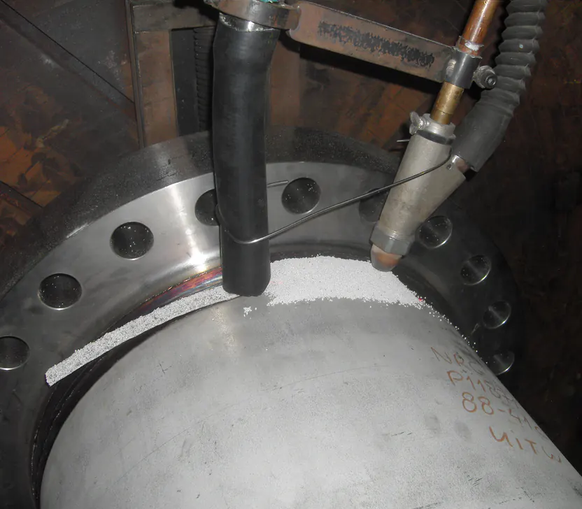
TIG loses a relatively large share of energy to radiation and the arc itself, whereas the flux bed in submerged arc welding traps nearly all the heat. When comparing processes, always apply these factors: a TIG weld at 1.5 kJ/mm of arc energy loads the material less than a submerged arc weld at the same arc energy.
What heat input does to the material
Higher heat input means slower cooling and a wider heat affected zone. Hardness drops, but grains grow, and coarse grain costs notch toughness. Lower heat input cools faster and keeps the grain fine, but in hardenable steels it raises the risk of martensite and cold cracking.
Every material and thickness therefore has a working window: enough heat to avoid hardening, little enough to preserve strength and toughness. The cooling time t8/5, from 800 down to 500 degrees Celsius, is the quantity that links the two. EN 1011-2 provides rules to estimate t8/5 from heat input, thickness, joint type and preheat.
Why it is critical for fine grain steels
Thermomechanically rolled and quenched and tempered fine grain steels such as S355ML, S460ML or S690QL owe their strength and toughness to a deliberately fine grain and a controlled microstructure. Excessive heat input destroys exactly that: grains coarsen, strength in the heat affected zone falls below the guaranteed value and impact toughness collapses. In quenched and tempered grades the tempered zone can soften as well.
Manufacturers therefore specify a maximum heat input and maximum interpass temperature, typically in the range of 1.0 to 2.5 kJ/mm depending on grade and thickness. These limits belong explicitly in the WPS and must be demonstrably observed in production. Going too low is equally wrong: cold cracking returns and preheating becomes necessary sooner.
Why it is critical for stainless and duplex
In austenitic stainless steel, excessive heat input causes wide heat tint, more distortion due to the high thermal expansion, and, with prolonged exposure between roughly 500 and 800 degrees Celsius, chromium carbide precipitation at the grain boundaries. That sensitisation locally destroys corrosion resistance. Keeping heat input low and limiting interpass temperature, usually to 150 degrees Celsius, is the rule.
Duplex stainless steel has a genuine window: too little heat gives excessive ferrite and nitrides, too much gives coarse grain and intermetallic phases. A typical range is 0.5 to 2.5 kJ/mm with alloy specific limits, as covered in our article on welding duplex stainless.
Heat input in qualification and the WPS
Under EN ISO 15614-1, heat input is an essential variable whenever impact or hardness requirements apply. Production welding may then exceed the qualified heat input by at most 25 percent and, where hardness requirements apply, undercut it by at most 25 percent. Welding the test piece neatly in the middle of the intended range therefore qualifies a narrow window that production will quickly outgrow.
A considered qualification strategy places the test weld deliberately at the edge of the intended working range. That requires calculating in advance which range of current, voltage and travel speed the workshop genuinely needs, and which heat input that implies per run.
Measuring and securing compliance in practice
Control starts with measurement. Modern power sources display current and voltage and often log them per weld, but travel speed remains manual: measure run length against arc time, or use bead size as a cross check. Spot checks by a welding coordinator or QC engineer make compliance demonstrable.
Practical safeguards:
- State current, voltage, travel speed and the resulting heat input per run in the WPS
- Train welders on the effect of weaving and bead size on heat input
- Verify the first production weld on critical work and record the measurement
If you are unsure of the correct window for a material or structure, that is a typical question for independent welding engineering advice.
Frequently asked questions
For general structural work, MAG heat input usually falls between 0.5 and 2.0 kJ/mm. Thin plate and root runs sit at the lower end, filling passes on heavy sections at the upper end. The governing value, however, is never a rule of thumb but the limit in the WPS and the material specification.
Per run. Each run has its own current, voltage and travel speed and therefore its own heat input. The run with the highest value governs the check against the maximum, while the root run with the lowest value often governs the cold cracking risk.
In TIG welding part of the arc energy radiates away and heats the electrode and shielding gas. In submerged arc welding the arc burns under a flux bed that traps the heat, so nearly all the energy enters the workpiece. EN 1011-1 therefore assigns k = 0.6 to TIG and k = 1.0 to submerged arc.
With pulsed welding you must use the true average power. Modern power sources report the arc energy or the time averaged product of current and voltage. Multiplying separately averaged current and voltage readings can give a misleading result with pulsing, so prefer the machine's energy measurement.
More from the knowledge centre
Have a welding or QA/QC question?
Ask the DEHAAS Welding & Quality Assistant, have your case reviewed by a specialist, or call us directly.